
Mono Fiber-optic Cannula
Mono Fiber-optic Cannula
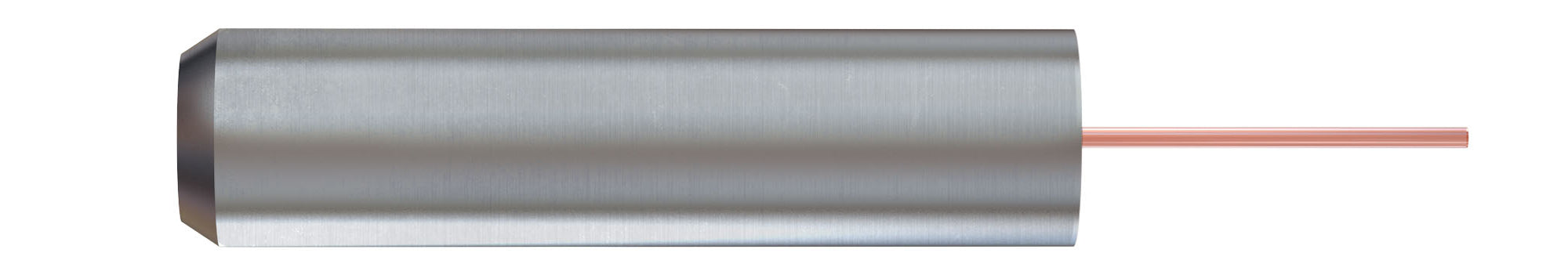
The Mono Fiber-optic Cannula is an assembly of a bare optical fiber, a fiber ferrule and a receptacle or a sleeve. One side of the ferrule is polished while the implantable part of the fiber protrudes from the opposite end of the ferrule. The ferrule is placed within the receptacle or sleeve to allow connection to the fiber-optic patch cord.
…generating
The Mono Fiber-optic Cannula is an assembly of a bare optical fiber, a fiber ferrule and a receptacle or a sleeve. One side of the ferrule is polished while the implantable part of the fiber protrudes from the opposite end of the ferrule. The ferrule is placed within the receptacle or sleeve to allow connection to the fiber-optic patch cord. The protruding fiber can be implanted into the body while the ferrule or the receptacle is attached to the skull. When the cannula is connected with the patch cord, it is possible to send light signals to and from tissue close to the fiber tip. It is imperative for in vivo optogenetics applications that the fiber-optic cannula allows for efficient, plug and play type connection to the fiber-optic patch cord.
A receptacle is a mechanical holder that defines the positions of the fiber tip and guides the connecting ferrule to the optical coupling position. For Mono Fiber-optic Cannulas we offer zirconia sleeves as the simplest form of a receptacle, alongside M2, M3 and slim magnetic receptacles.
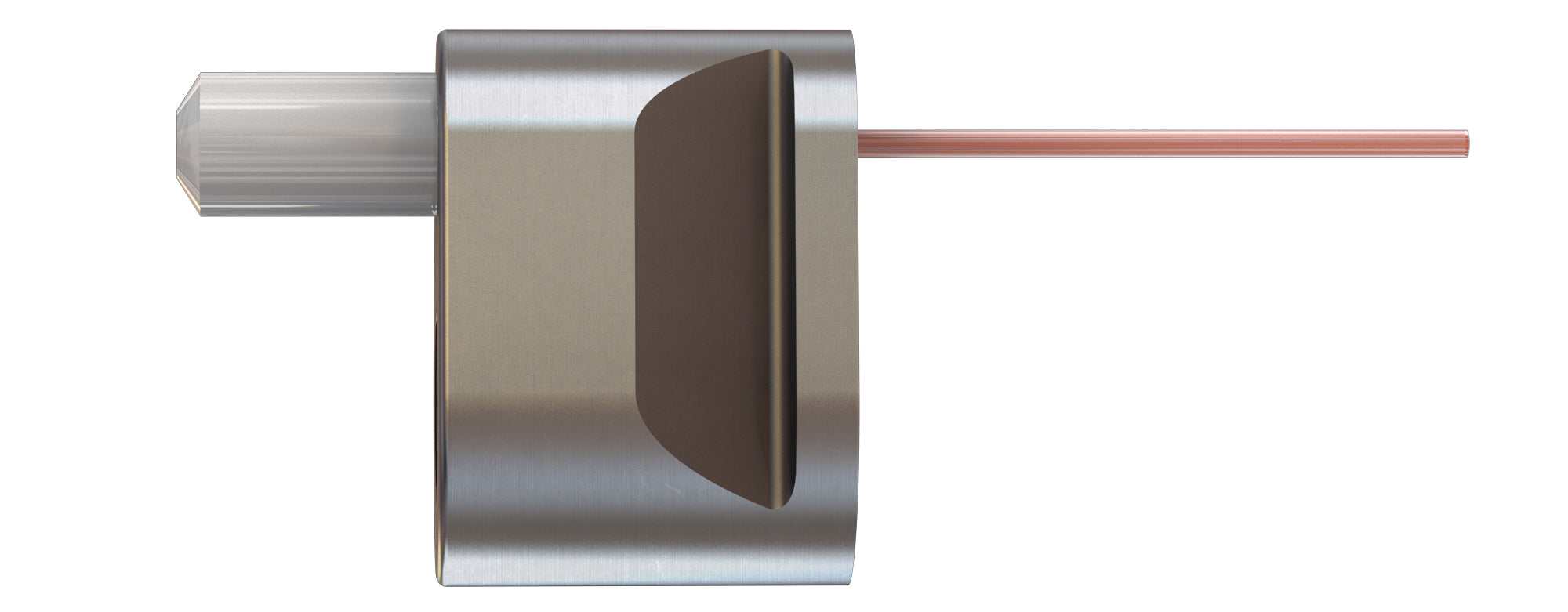
Low Profile Cannulas are designed to minimize the height over the animal's head. The patch cord connection is in the same axis as the animal's body instead of hanging over its head. This cannula allows for the fiber optic implantation in a standard stereotaxic dorso-ventral axis, but the interconnection are along the antero-posterior plane. This cannula design minimizes the pressure applied on the animal's head during the connection/disconnection of the patch cord. Furthermore, the Low Profile Cannula facilitates the motion of the animal’s head in restraint areas.
NOTES :
- The tolerance on the length of the protruding fiber is better than 0.1 mm.
- Sleeves required to connection with a patch cord are ordered separately.
- Stereotaxic Cannula Holder (SCH) for 1.25 and 2.5 mm diameter ferrule is available for implantation to securely hold the Mono Fiber-optic Cannulas.
- Receptacle adapters are available for M2 and M3 receptacles to use with SCH.
- A specific version is available for LPB90(P) receptacle.
- Low-Profile Cannula receptacle is only available with borosilicate optical fiber type.
| Comparison Table for Fiber-optic Cannulas | ||||
| Fiber-optic Material | Borosilicate | Silica / Silica | Silica / Polymer | Plastic |
| Core | Glass | Glass | Glass | Plastic |
| Cladding | Glass | Glass | Polymer | Polymer |
| Protective layer | — | Polyimide | — | — |
| Numerical Aperture | 0.66 | 0.22 - 0.37 | 0.48 - 0.57 | 0.50 - 0.63 |
| Chemical resistance | ✓ Good | ★ Excellent | ✕ Poor | ✕ Poor |
| Mechanical resistance | ✕ Poor | ★ Excellent | ✓ Good | ✓ Good |
| Scratch resistance | ✓ Good | ★ Excellent | ✕ Poor | ✕ Poor |
| Auto-fluorescence | ✓ Good | ★ Excellent | ✓ Good | ✕ Poor |
| Recommended use | ||||
| Fiber photometry | ★ BEST | ✓ Good | ✓ Good | ✕ Not recommended (High auto-fluorescence) |
| Optogenetics (LED source) | ★ BEST | ✕ Not recommended (Low NA) | ✓ Good | ✓ Good |
| Optogenetics (Laser source) | ✓ Good | ★ BEST | ✓ Good | ✓ Good |
| Core Material | Core Diameter (μm) |
Outer Diameter (μm) |
NA | Buffer Color | Outer Layer | Code |
| Glass | 50 | 70 | 0.22 | Yellow | Polyimide | 050/070-0.22 |
| 60 | 75 | 0.37 | Yellow | Polyimide | 060/075-0.37 | |
| 100 | 125 | 0.22 | Yellow | Polyimide | 100/125-0.22 | |
| 100 | 125 | 0.37 | Yellow | Polyimide | 100/125-0.37 | |
| 100 | 125 | 0.66 | Clear | Borosilicate | 100/125-0.66 | |
| 200 | 240 | 0.22 | Yellow | Polyimide | 200/240-0.22 | |
| 200 | 245 | 0.37 | Yellow | Polyimide | 200/245-0.37 | |
| 200 | 230 | 0.48 | Clear | Polymer | 200/230-0.48 | |
| 200 | 250 | 0.66 | Clear | Borosilicate | 200/250-0.66 | |
| 300 | 330 | 0.48 | Clear | Polymer | 300/330-0.48 | |
| 300 | 370 | 0.22 | Yellow | Polyimide | 300/370-0.22 | |
| 300 | 360 | 0.37 | Yellow | Polyimide | 300/360-0.37 | |
| 400 | 480 | 0.22 | Yellow | Polyimide | 400/480-0.22 | |
| 400 | 470 | 0.37 | Yellow | Polyimide | 400/470-0.37 | |
| 400 | 430 | 0.48 | Clear | Polymer | 400/430-0.48 | |
| 400 | 430 | 0.66 | Clear | Borosilicate | 400/430-0.66 | |
| 600 | 630 | 0.48 | Clear | Polymer | 600/630-0.48 | |
| 600 | 710 | 0.22 | Orange | Polyimide | 600/710-0.22 | |
| 600 | 710 | 0.37 | Yellow | Polyimide | 600/710-0.37 | |
| Plastic | 240* | 250 | 0.63 | Clear | PMMA | 240/250-0.63 |
| 480* | 500 | 0.63 | Clear | PMMA | 480/500-0.63 |
* Plastic fibers are not available with conical tip (C45, C60), 45° mirror tip (MA45) or diffuse layer tip (DFL).


| Description | Drawing | Code | Note |
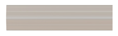
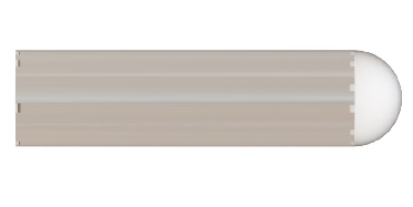
| Flat Tip |
|
FLT | |
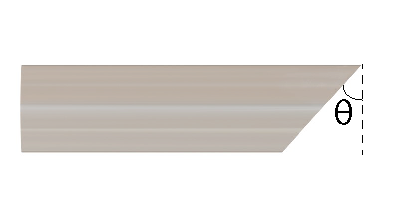
| Angled Tip |
|
A45 A60 |
Standard angles: 45°; 60° Other angles on request (max 60°) |
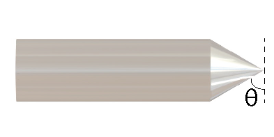
| Conical Tip |
|
C60 |
Rounded tip thickness: ~0.1x to 0.2x core diameter Standard angle: 60° Other angles on request (max 60°) |
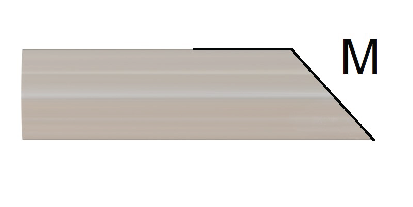
| 45° mirror Tip |
|
MA45 | |
| Diffuser layer Tip |
|
DFL | |
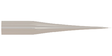
| Taper Tip |
|
TAPER |
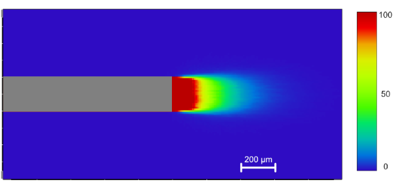
The light propagation into brain tissue will vary with the optical fiber type and the light source parameters. It can be visualized in this Application Note (the French version is available here ).
| Receptacle Type | ZF1.25 -ZF2.5 MF1.25 - MF2.5 | SM3 - SM3(P) RM2 - RM2(P) | SMR | LPB90(P) |
| Connection type | sleeve | screw | magnetic twist | sleeve |
| Transmission | 80 % | 80 % | 70 % | 60 % |
| FiberLength (mm) | 0 to 50 | 0 to 50 | 0 to 50 | 1.0 to 30 |
| LengthTolerance (mm) | +/-0.1 | +/-0.1 | +/-0.1 | +/- 0.2 |
| Angle (deg) | 0 | 0 | 0 | 90 +/- 2 |
| MRI compatible | yes (zirconia only) | yes (peek version) | no | yes (peek version) |
Related products
-
Choose your option
-
Choose your option
-
Choose your option
-
Choose your option
-
Choose your option
-
Choose your option


