


Splitter Branching Fiber-optic Patch Cords
Splitter Branching Fiber-optic Patch Cords
The Splitter Branching Fiber-optic Patch Cord evenly splits the light from a large core diameter connectorized optical fiber into 2 or more branches of smaller core diameter connectorized optical fibers. A 15 cm long large core optical fiber helps obtain uniform distribution of light before a launch into 2 or more optical fibers bundled inside the central tubing. A 2-branch Splitter Branching Fiber-optic Patch Cord typically outputs around 16 % of the input power.
These patch cords are typically used in optogenetics for sharing powerful laser or LED light sources between several fibers and conserving uniform light intensity (mW/mm2) among their outputs.
The standard Splitter Branching Fiber-optic Patch cords has 2 branches, more are available if requested. A 2-branch patch cord splitter typically outputs around 16 % of the power entering the input optical connector, with variations depending on fiber type and the area recovery ratio.
…generating
The Splitter Branching Fiber-optic Patch Cord evenly splits the light from a large core diameter connectorized optical fiber into 2 or more branches of smaller core diameter connectorized optical fibers. A 15 cm long large core optical fiber helps obtain uniform distribution of light before a launch into 2 or more optical fibers bundled inside the central tubing. A 2-branch Splitter Branching Fiber-optic Patch Cord typically outputs around 16 % of the input power.
These patch cords are typically used in optogenetics for sharing powerful laser or LED light sources between several fibers and conserving uniform light intensity (mW/mm2) among their outputs.
The standard Splitter Branching Fiber-optic Patch cords has 2 branches, more are available if requested. A 2-branch patch cord splitter typically outputs around 16 % of the power entering the input optical connector, with variations depending on fiber type and the area recovery ratio.
|
Optical Fiber Core Diameter ( μm ) |
Number of Output Fibers |
Internal Input Optical Fibre Core Diameter ( μm ) |
Coupling into Each Output |
| 100 | 2x | 240 | 16 % |
| 3x | 240 | 16 % | |
| 4x | 480 | 4 % | |
| 200 | 2x | 480 | 16 % |
| 3x | 480 | 16 % | |
| 4x | 730 | 7 % | |
| 400 | 2x | 960 | 16 % |
| 3x | 960 | 16 % | |
| 4x | 960 | 16 % |
This approach uses a 50 mm long metal tube with a 6.35 mm diameter to protect the passage from 1 to several fibers. The length of patch-cord from the metal tube to the patch-cord split, called the central jacket, can be protected using a different jacket type. Splitter patch cords are not suitable for short cables less than 30 cm long. This version allows improved splitting of laser light over older models. In all other applications, the Splitter Branching Patch Cords maintain the same high-quality performance as our legacy Standard Branching Patch Cords.
- Minimum total cable length is 35 cm.
- The Type-A (AX identifier) patch cords have no central jacket, with the splitter starting at the metal tube. The split is done 17.5 cm from the input.
- The Type-B (BX identifier) patch cords have a central jacket covering the length between the metal tube and the splitter. The split is done at 15 cm from the output.
- Not recommended for high power application
The maximum input power tested in continuous is 100 mW for wavelength between 450 and 650 nm. Please ask our technical support to use with higher power or different wavelength range.
| Core/Cladding Material | Core Diameter (μm) | Cladding (μm) | Buffer (μm) | NA | Fiber-Optic Code* |
| Silica/Silica | 100 | 110 | 125 | 0.22 | 100/110/XXX-0.22 |
| 100 | 110 | 125 | 0.37 | 100/110/XXX-0.37 | |
| 200 | 220 | 240 | 0.22 | 200/220/XXX-0.22 | |
| 200 | 220 | 245 | 0.37 | 200/220/XXX-0.37 | |
| 400 | 440 | 480 | 0.22 | 400/440/XXX-0.22 | |
| 400 | 440 | 470 | 0.37 | 400/440/XXX-0.37 | |
| Silica/Polymer | 200 | 230 | 500 | 0.48 | 200/230/XXX-0.48 |
| 200 | 230 | 500 | 0.57 | 200/230/XXX-0.57 | |
| 400 | 430 | 730 | 0.48 | 400/430/XXX-0.48 | |
| 400 | 430 | 730 | 0.57 | 400/430/XXX-0.57 | |
| Plastic/Plastic | 240 | 250 | - | 0.63 | 240/250/XXX-0.63 |
| 480 | 500 | - | 0.63 | 480/500/XXX-0.63 | |
| 735 | 750 | - | 0.63 | 735/750/XXX-0.63 |
* XXX is representative of the jacket code, see Jackets tab to choose the best one for your needs
| Termination Codes for Fiber-Optic Patch cords | ||
| Description | Product | Termination Code |
| FC Connector with Zirconia Ferrule FC Connector with Metal Ferrule |  | FC FCM |
| FC/APC Connector with Zirconia Ferrule* FC/APC Connector with Metal Ferrule* |  | FCA FCMA |
| SMA Connector with Metal Ferrule |  | SMA |
| Zirconia Ferrule OD 1.25 mm | 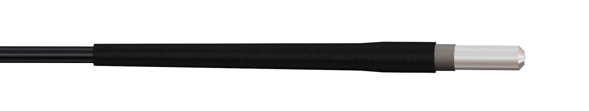 | ZF1.25 |
| Zirconia Ferrule OD = 1.25 mm with Flange Zirconia Ferrule OD = 1.25 mm with Peek Flange |  | ZF1.25(F) ZF1.25(FP) |
| Metal Ferrule OD 1.25 mm |  | MF1.25 |
| Zirconia Ferrule OD = 2.5 mm |  | ZF2.5 |
| Zirconia Ferrule OD = 2.5 mm with Flange Zirconia Ferrule OD = 2.5 mm with Peek Flange |  | ZF2.5(F) ZF2.5(FP) |
| Metal Ferrule OD = 2.5 mm |  | MF2.5 |
| Slim Magnetic Connector |  | SMC |
| M3 Connector |  | CM3 |
| M3 Connector Peek Plastic |  | CM3(P) |
| M2 Connector |  | CM2 |
* FC/APC Connectors available for Fiber-Optic Patch Cords NA 0.22 only.
| Termination Codes for Dual Fiber-Optic Patch cords (1 connector side) | ||
| Description | Product | Termination Code |
| Dual Ferrule with a guiding pin Pitch from 0.7 mm to 1.7 mm |  | DF□.□ |
| Guiding Socket* Pitch from 0.7 mm to 1.7 mm |  | GS□.□ |
*Recommended termination for Dual Fiber-Optic Patch cord.
| Comparison Table : Protective Jacket | |||||||||
| Composition | Code | Description | Color | OD (mm) | Linear mass (g/m) | Flexibility | Fiber break protection | Fiber pull protection | Proposed usage |
 | 900 | Hytrel loose tube 0.9 | Black* | 0.9 | 0.5 | Excellent | Low | Low | Cable to small freely-moving animal (mice) |
 | 1000 | Hytrel loose tube 1.0 mm | Black* | 1.0 | 0.5 | Excellent | Low | Low | Cable to small freely-moving animal (mice) |
| 1100 | Hytrel loose tube 1.1 mm | Black* | 1.1 | 0.5 | Excellent | Low | Low | Cable to small freely-moving animal (mice) |
 | 3000 | PVC jacket 3 mm | Black | 3.0 | 5.8 | Low | Good | Excellent | General use cable |
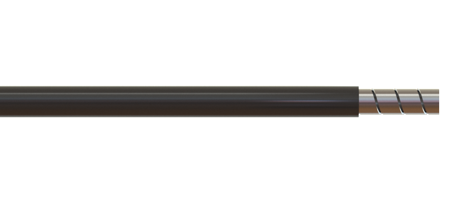 | LWMJ | Stainless monocoil with PVC 2.4 mm | Black | 2.4 | 7.5 | Good | Good | Good | Freely-moving animal light delivery with large mice or rat |
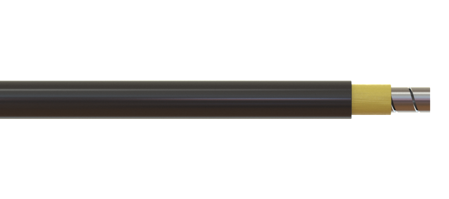 | PKMJ | Stainless monocoil with kevlar and PUR 3.0 mm | Black | 3.0 | 11 | Good | Excellent | Excellent | Best compromise between flexibility and robustness |
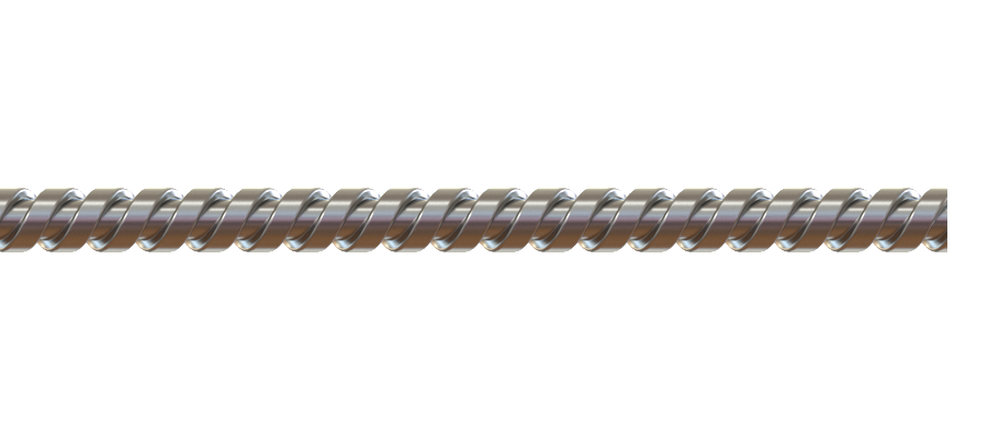 | ARMO | Stainless armor 2.3 mm | Silver | 2.3 | 9.2 | Low | Excellent | Excellent | Preferred for maximum robustness |
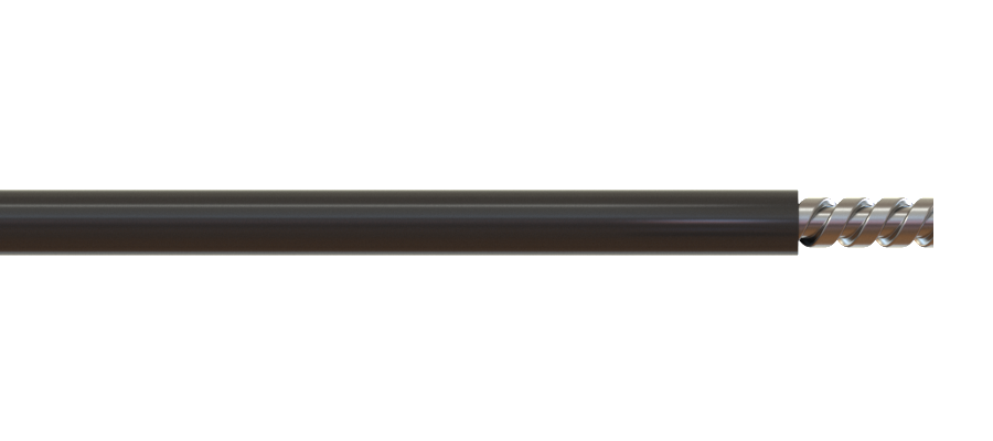 | ARBK | Stainless armor with PVC 3 mm | Black | 3.0 | 15 | Low | Excellent | Excellent | Preferred for maximum robustness |
* Other color available on request.
Jacket availability may vary with optical fibre type
Related products
-
Choose your option
-
Choose your option

