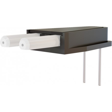
Dual Fiber-optic Cannula

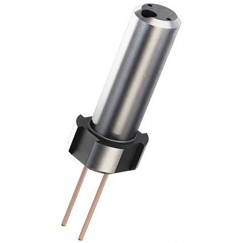
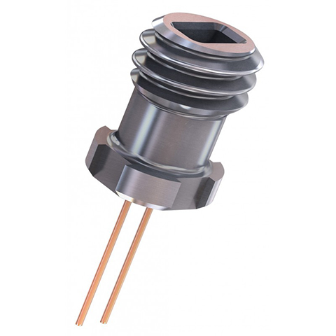
- Dual Fiber-optic Cannula features two implantable fibers at a prescribed distance and protrusion length held by a single receptacle. If the distance between two fibers ranges between 0.5 and 2.0 mm, both optical fibers are embedded into a single connection using DF or GS type dual connector. For distances above 2.0 mm, the solution is two separate ferrules in a baseplate that connect using mating sleeve or magnetic connector.
These cannulas are perfectly suited for a bilateral chronic experiment. Alternative would be to use two mono-fiber cannulas; however positioning two cannulas with stereotaxic equipment, one at a time, has a greater likelihood of positioning errors, prolongs the duration of the operation, complicates the fixation of the cannulas and increases the minimum possible distance between the two fiber tips.
With these Dual Fiber-optic Cannulas, the insertion of the fiber is faster (single shot), while the distance between the fiber tips and the protrusion depth are factory set, precisely. The precision fiber-to-fiber mating of the cannula with the corresponding fiber-optic patch cord is vital for good coupling and this is achieved by a guiding pin or by a guiding socket.
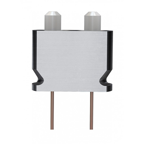
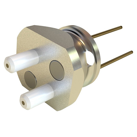
Two types of receptacles are currently available for the larger distance between optical fibers; split-sleeve and magnetic. They both consist of precision machined holders that house zirconia ferrules and determine the spacing between the ferrule centers. The first type of a two-ferrule cannula connects to a pair of patch cords terminated with 1.25 mm ferrules by using two zirconia sleeves (ID 1.25 mm). In the other case, the holder also includes a pair of magnets, so that the cannula can connect to a pair of SMC connectorized patch cords.
Two-ferrule Low Profile Cannulas are designed to minimize the height over the animal's head. The patch cord connection is in the same axe than the animal's body instead of hanging over its head. This cannula allows for the fiber-optic implantation in a standard stereotaxic dorso-ventral axis, but the interconnection is along the antero-posterior plane. This cannula design minimizes the pressure applied on the animal's head during the connection/disconnection of the patch cord. Furthermore, the Low Profile Cannula facilitates the motion of the animal’s head in restraint areas. On custom basis, we can do Two-ferrule Low Profile Cannulas with the appropriate fiber pitch distance, up to 10 mm.
Notes:- Angled and conical tips are offered to facilitate the insertion of the fiber-optic in the tissue.
- Dual Fiber-optic Cannula with guiding pin (DF) is implanted using the Stereotaxic Cannula Holders 2.5 (SCH_2.5).
- Guiding Socket dual cannulas (GS) requires a specific adapter available for 1.25 or 2.50 mm Stereotaxic Cannula Holders.
- Two-Ferrule Cannula with sleeve or magnetic are implanted using the Stereotaxic Cannula Holders 1.25 mm (SCH_1.25)
- For Two-Ferrule Cannulas (TFC or TSM) with distances between fibers (pitch) between 1.8 to 2.5 mm, you should make sure to use compatible patchcord termination having 1.8 mm maximum diameter.
Comparision Table for Cannulas Optical Fiber Type Optical Fiber Type Borosilicate Silica/Silica Silica/Polymer Plastic Core Glass Glass Glass Plastic Cladding Glass Glass Polymer Polymer Protective Layer - Polyimide - - Numerical Aperture 0.66 0.22 - 0.37 0.48 - 0.57 0.50 - 0.63 Chemical Resistance Good Excellent Poor Poor Mechanical Resistance Poor Excellent Good Good Scratch Resistance Good Excellent Poor Poor Auto-Fluorescence Good Excellent Good Poor RECOMMENDED USE : Fiber Photometry BEST Good Good N/A
Optogenetics (LED Source) BEST Not recommended
(low NA)
Good N/A Optogenetics (Laser Source) Good BEST Good N/A -
* Mass given for pitch = 3.0 mmReceptacle Type Dual Ferrule
(DF)Guiding Socket
(GS)
Two Ferrule
(TF)Magnetic
(TSM)Low-Profile
(LPB)Connection type sleeve screw 2 sleeves
magnetic 2 sleeve Transmission 80 % 80 % 80 % 70 % 60 % Pitch (mm) 0.7 to 1.7 0.7 top 2.0 2.0 to 10 2.0 to 10 2.0 to 10 Fiber Length (mm) 0.0 to 50 up to 50 up to 50 up to 50 1 to 30 LengthTolerance (mm) +/- 0.1 +/- 0.1 +/- 0.1 +/- 0.1
+/- 0.2 Angle (deg) 0 0
0
0 90 +/- 2 Mass (mg)
375
265
265*
300*
MRI compatible no no no**
no yes
** MRI compatible version with peek receptacle base is available on request -
-
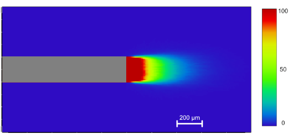
The light propagation into brain tissue will vary with the optical fiber type and the light source parameters. It can be visualized in this Application Note (the French version is available here).
Description Drawing Code Note Flat Tip 
FLT Angled Tip 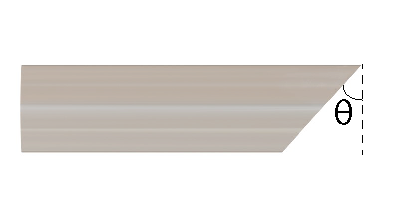
A45
A60
Standard angles: 45°; 60°
Other angles on request (max 60°)
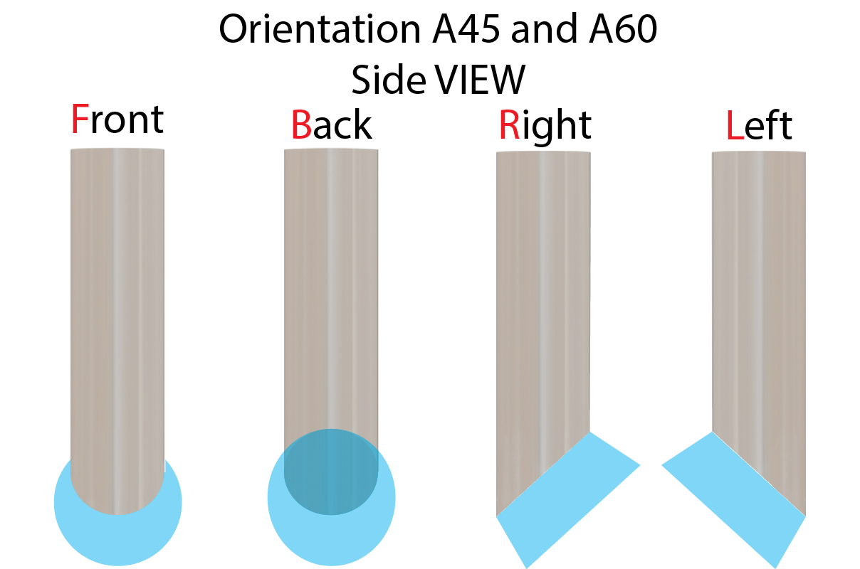
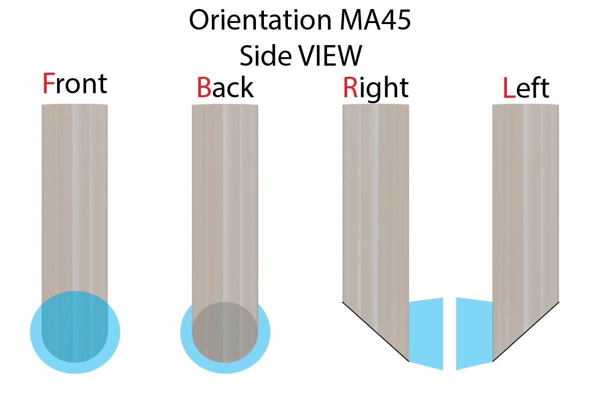
For orientation see table bellow
Conical Tip 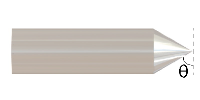
C60 Rounded tip thickness: ~0.1x to 0.2x core diameter
Standard angle: 60°
Other angles on request (max 60°)
45° mirror Tip 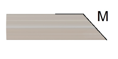
MA45 For orientation see table bellow Diffuser layer Tip 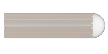
DFL Taper Tip 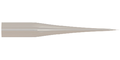
TAPER
Fiber orientation:
- le choix d'une sélection entraîne une actualisation complète de la page

